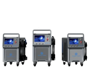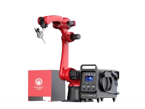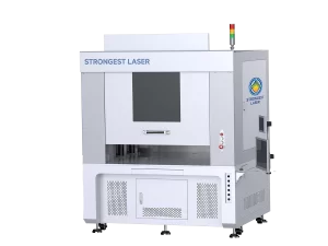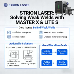
The STRION LASER AW Robotic Welding System offers high-precision, automated welding solutions for industrial applications. Proper installation is critical for achieving consistent weld quality, system stability, and extended equipment life. In this guide, we cover key installation steps, including electrical signal setup, torch assembly, laser spot inspection, wire feeding, shielding gas management, and focal offset adjustment.

Electrical Signal Installation Guidelines
Voltage Requirements
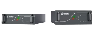
Except for the AW-850 model, all AW series systems operate on 220V. Excessively high or low voltage can cause unstable operation or even permanent damage to the equipment. To ensure proper functioning, voltage fluctuations should be maintained within ±10% of the nominal value.
Importance of Grounding
Reliable grounding is critical for both equipment safety and stable operation.
If the site’s distribution box lacks a ground wire, install a temporary ground by driving an 80cm–1m iron rod into moist soil.
Secure the system’s ground wire to the top of the rod using a bolt or welding.
Verify grounding using a multimeter by measuring:
Line (L) to Neutral (N)
Line (L) to Ground (G)
Neutral (N) to Ground (G)
Proper grounding indicators:
Voltage between Line and Ground should be equal to Line and Neutral voltage.
Voltage between Neutral and Ground should be close to 0V (within 10V is acceptable).
Warning: A significant voltage difference between Neutral and Ground indicates poor grounding or equipment leakage, which may compromise system safety and performance.

Torch Head Installation
Key Points for Torch Head Installation
The primary focus during torch head installation is the QBH connector. Before inserting the fiber, ensure the surrounding installation environment is clean and free from dust or debris.
Installation Steps
Rotate the torch head to a horizontal position.
Insert the fiber carefully.
Before insertion, remove the fiber cap and inspect the fiber end-face for dust or contamination.
Do not touch the fiber end-face with your fingers.
Important: Never insert the fiber vertically into the torch head. This can cause misalignment or damage.

Spot Check
If the welding arc appears weak or unstable, the first step is to inspect the protective and focusing lenses. Replace any damaged or contaminated lenses.
After replacing the lenses, you can use a piece of white paper to check the integrity of the laser spot.
This method allows you to identify potential issues with beam alignment or the reflector lens, even when the protective and focusing lenses are in good condition.

Lens Replacement

When replacing any lenses, avoid touching the lens surfaces with your hands. If it is necessary to handle them, hold the lenses by the edges only.
For the focusing and collimating lenses in the welding gun, the convex side should face the nozzle.
Before replacing the lenses, prepare lint-free cloths, high-purity alcohol, and masking tape. Wipe off any dust on the exterior of the gun before disassembly. When removing the focusing or collimating lens, quickly seal the opening with masking tape to minimize dust entering the gun body.
Wire Feeding Angle and Focal Position
The first step in laser welding is accurately locating the focal point. It is recommended to use stainless steel to find the focus, with laser power set around 200–300 W.
During this process, the robot-controlled laser beam should move along the Z-axis to identify the position where the laser energy is strongest.

After confirming the focus, adjust the wire to the optimal position for best welding results. Remember the current height after finding the focus, then adjust the torch length to set the wire height. The wire should just touch the material surface, slightly behind the red light position.

Shielding Gas in Laser Welding
Types of Shielding Gas – Common shielding gases include helium, argon, and nitrogen. Each gas affects welding performance differently, so select the appropriate type based on the specific application.
Gas Flow Rate – The flow rate of shielding gas significantly impacts welding quality. Too high or too low a flow can reduce protection or cause defects like porosity. Adjust the flow rate according to the material and welding conditions.
Relation to Plasma Shielding – Shielding gas helps suppress plasma shielding. Incorrect flow rates can lead to excessive or insufficient plasma formation, affecting weld quality. Proper flow ensures optimal plasma suppression and consistent weld seams.
Definition of Defocus in Laser Welding
Positive and Negative Defocus – When the laser energy center is below the material surface, it is called negative defocus; when above, it is positive defocus. If aligned with the material surface, it is zero defocus or focus.
Focus Position – The point where the laser spot diameter is smallest and energy is strongest. This is the most commonly used welding state. Once the focus is confirmed, it is generally fixed and not adjusted during welding.
Negative Defocus – The spot diameter is slightly larger than at the focus, increasing with distance from the focus. Suitable for deep penetration welding to reduce spatter.
Positive Defocus – The spot diameter is also slightly larger than at the focus. Ideal for surface sealing, continuous welding, or applications with low penetration requirements.

Correct installation of Strion Laser AW welding machines not only guarantees safety but also maximizes welding efficiency and quality. By paying close attention to electrical setup, optical adjustments, wire feeding, shielding gas, and defocus calibration, operators can achieve consistent and reliable welding results.